
Need for Feed Units: 2nd Installment
Contributed by John Zagar
Edited by Jo Gardner
In the 1st Zagar Need for Feed Units installment, we covered general variables in feed unit selection. Mechanical, hydraulic, and pneumatic feed units each have different features and functions that perform best when used for certain applications. The feed mechanism, which usually extends the spindle in a quill, can be driven mechanically, hydraulically, or pneumatically. A feed unit typically can perform both rapid advance and controlled feed and provides position feedback through limit sensors or encoder/resolver feedback for integration into machine control.
This 2nd installment by Zagar Inc. continues to expound on the variables involved, in order to help you optimize feed unit utilization, avoiding a slow production rate and frustrated machinists.
Mechanical Feed Units
The major types of mechanical feed units to consider are ballscrew feed, cam feed, gear-driven, and leadscrew.
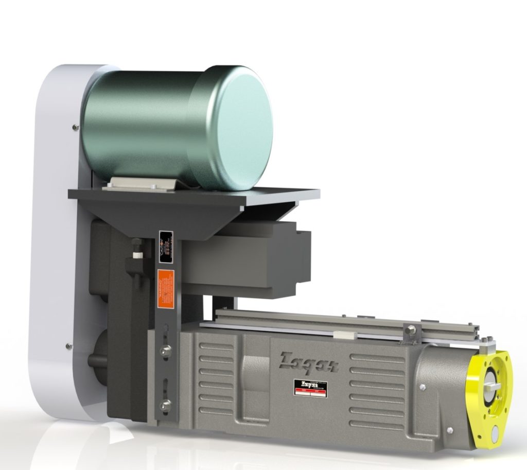
Ballscrew Feed Unit technology has become vital to feed unit capability, offering flexibility, programmable controls, power, and precision. The Zagar ballscrew unit provides the feed through transmission, such as a coupling, belt and pulleys, or gears from the feed motor (usually a servomotor). Some feed units have the quill attached directly to the ballscrew nut, while others have the ballscrew nut attached to the quill by a connection device. In the latter type, the ballscrew is offset from the centerline access of the spindle and quill. A direct coupling to the ballscrew nut provides high-efficiency thrust on the tool’s centerline axis. This also results in minimized deflection, a major consideration in precision tooling.
In a Cam Feed Unit, a cam follower attached to the quill follows the path of either a rotary drum cam, or a linear (kidney-shaped) cam. As the cam rotates slowly through some means of speed reduction (via a gear box or a harmonic drive), it advances the quill in relation to the path that is cut into the cam. The harmonic-drive type of speed reducer is a high-ratio, mechanical device. The speed reducer turning the cam, with reductions up to 200:1, is often turned by a second belt or pulley driven by the same motor used to rotate the spindle. Cam feed units may also utilize a gear transmission connecting the speed reducer and the spindle. Each method results in synchronization of the spindle speed and quill feed. Varying combinations of belts and pulleys connecting the spindle to the speed reducer adjust for speed and feed requirements.
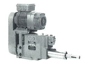
The cam feed unit is the least flexible, but longest lasting of mechanical feed units. The cam has a permanently machined path cut into it for the drilling cycle, including rapid advance, feed, and retract sections. The only way to adjust the cycle is to install a new cam which can be an expensive prospect. The cam is a custom part, made from a standard blank, more expensive than a stock part. Its down time for replacement can be extensive, depending on how deep inside the unit the cam is located. When used for a high-production line, however, the cam feed unit is attractive for its rock-solid consistency in part-feature repeatability.
Gear Feed Units employ a gear drive for transmission from source to output. There are many types of gear feed units, and the gear drive can be used for the spindle and/or the quill feed.
The largest percentage of gear units are configured as tapping units, because the gearing lends itself so well to synchronized rotation and feed. The gear transmission can be a rack-and-pinion assembly, a gear-reduction drive synchronized with the spindle rotation, or a gear transmission driving a leadscrew. The tap pitch is altered by changing the two drive gear ratio, or, with a leadscrew unit, by changing the leadscrew and leadscrew-nut pitch.
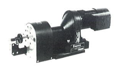
Leadscrew tapping units advance the tap at the pitch of the leadscrew. When you want to change the tap pitch, you have to change the leadscrew and the leadscrew nut, making it important for machine operators to be able to access this part of the unit and perform the changeover. The time needed to change the leadscrew (5 to 20 minutes) must be factored into the production requirements for this type of unit. (If this downtime is deemed unacceptable, a programmable ballscrew unit may be a better alternative, because it allows quick entry of pitch, part number, and tap size, for example, depending on how it is programmed.
Low-speed operations usually require gear reduction of the motor. The most common type of motor used for these units is a reversing brake motor, which provides almost instant deceleration and reversal for tap retraction. Drilling can be performed with these units only if the leadscrew is removed.
For all mechanical feed units, especially leadscrew or cam units, Zagar, a distributor for Jarvis Cutting Tools, recommends using high quality Jarvis Taps for higher endurance and production, before requiring replacement.)
This Article will be continued June 23rd in a third installment covering Pneumatic and Hydraulic Feed Units.